Monthly Archives: January 2017

Of mice and men (but mostly mice)

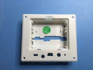
Mice for the QL always have been kind of a problem. In the age that predated USB by two decades there was simply not the one mouse standard to rule them all. Every system did pretty much its own thing and getting a mouse that actually worked wasn’t that easy to begin with. In fact I have never even owned a mouse for the QL that worked right out of the box, every mouse had its electronics ripped out and replaced by something else to work with my trusty SuperQBoard clone. This posed a problem for me as I have recently resurrected my trusty QL but apparently the mice were thrown away at some point or other. Jochen Hassler kindly gifted me one of his old mice, but it was brown with age, the ergonomics is questionable and I really didn’t remember what a pain the ball-based mice were to use compared to their optical brethren.

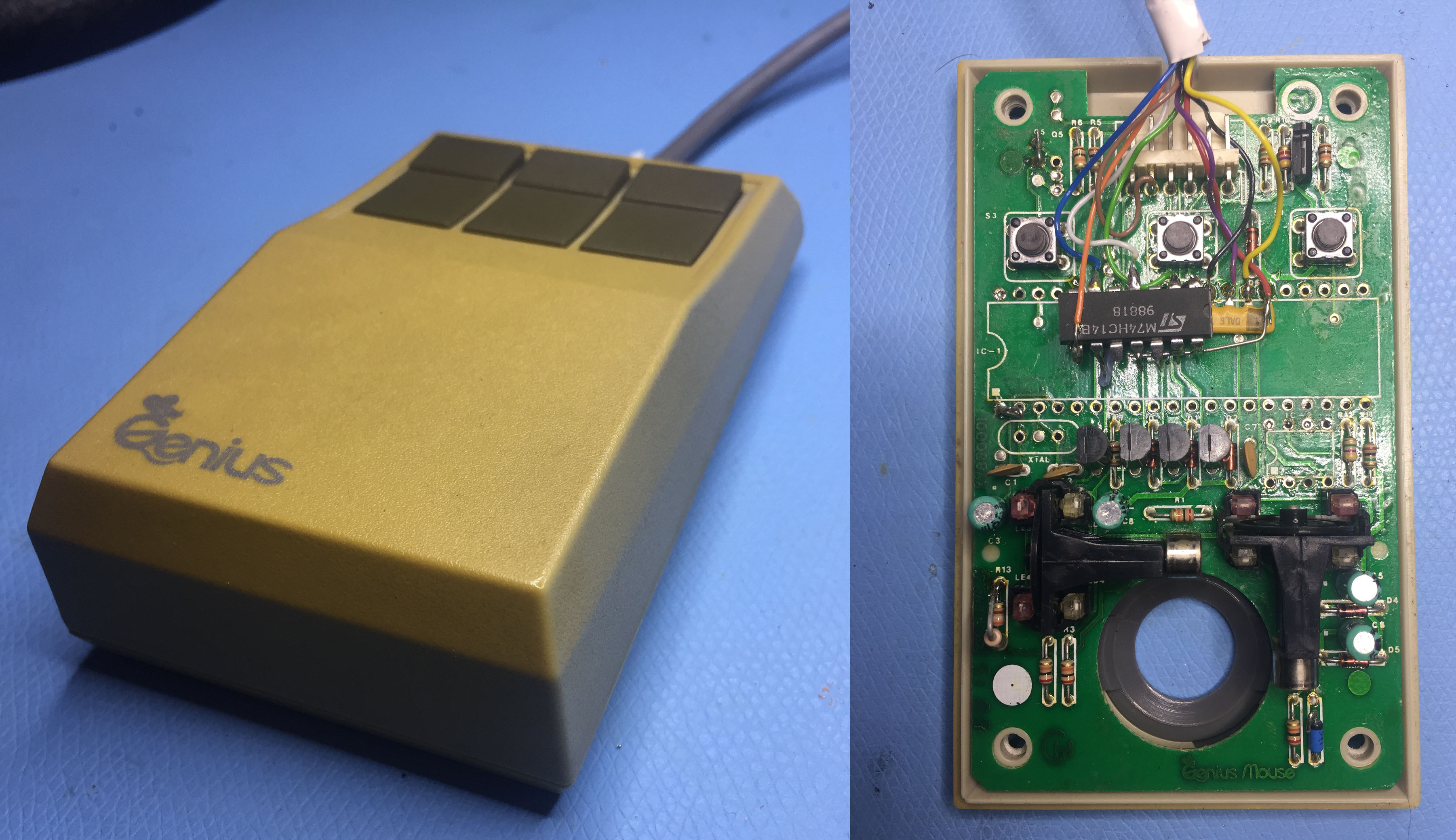
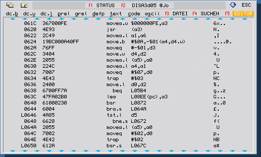
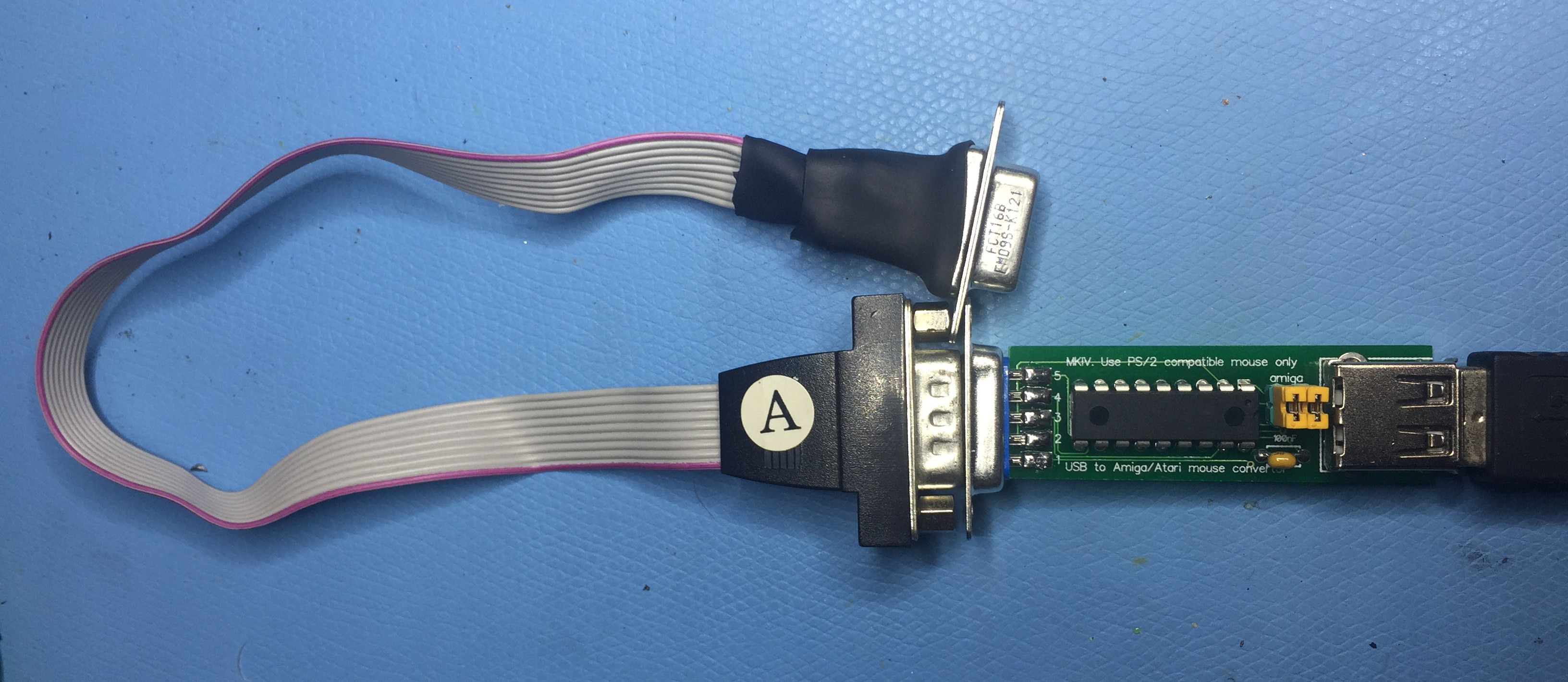
This lead to the idea of implementing a converter, like taking a cheap Arduino Pro Mini to interface a modern USB mouse to the old SuperQBoard port. Fortunately before starting such a project I had a look at what’s already there and found the “New MKIV Amiga/Atari USB mouse adapter” for about 16€ plus postage. Atari mice are generally the type used for the QL, too, so I just bought it. The first tests a few days later weren’t that encouraging, nothing worked at all. So I had a look at the schematics of the SuperQBoard and found out that although electronically it’s Atari/QIMI compatible, it used a completely different pin layout!

Long story short, this is the pin mapping I came up with

SuperQBoard QIMI/Atari Signal
1 9 Right button
2 6 Left button
3 1 XB
4 3 YA
5 7 +5V
6 4 YB
7 2 XA
8 5 n/c or middle button
9 8 GND

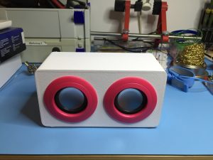
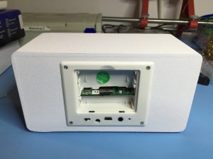
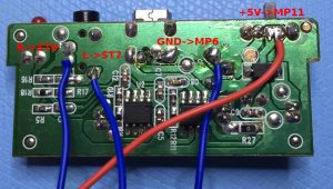
After building a suitable adapter cable the optical mouse began to light up, indicating the power is there, and the buttons worked, too, indicating a working mouse protocol on the USB side (or rather PS/2 side really, the adapter only works with mice that can speak the PS/2 protocol over the USB connector) but the pointer only moved very erratically. So after some hair pulling (as if I still had any) I went back to the schematics and saw that apparently unlike QIMI my SuperQBoard clone only had pull-up resistors on the mouse button lines and not on the lines responsible for X/Y movement! So I decided to integrate them quick&dirty style into the adapter cable:

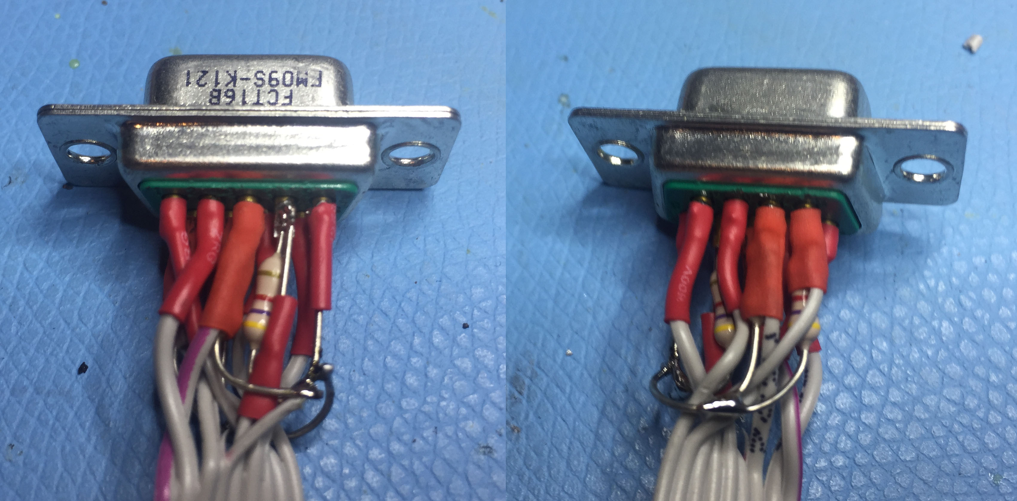
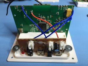
Quick&dirty integration of pull-up resistors…

… but in the end, who can tell

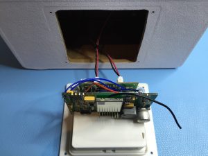
And what can I say, it worked so smoothly it was a pure joy to use.

So, lessons learned:

  • The adapter might be used together with a QIMI interface right out of the box
  • SuperQBoards used a pinout different from QIMI
  • SuperQBoards might be lacking the necessary pull-up resistors
  • Hardware tinkering is still fun

New QPC2, DISA and more

Every year I take the birthday of my daughter as an incentive to get stuff out of the door.

So this year I present to you:

QPC2 v4.05

This is mostly a bugfix release. It includes the latest SMSQ/E 3.28. One option was added that instead of a fixed resolution it can use the maximum resolution of the current monitor. Select “Max” as a resolution to do this.

Get it from the Downloads page.

… but there is more

The disclaimer for the following software: you may not sell the software and they come with no support whatsoever.

DISA

My old friend Jochen Hassler was over for dinner a few days ago and I asked him if I may release his software. He said yes, so here I present to you DISA, a pretty revolutionary disassembler at its time. V3.04 was the last official release done by Jochen in 1999. I adapted the source code for high colour in 2003, but this release 3.05 has never left my hard drive until today. So here they are:

DISA 3.04
DISA 3.05
DISA examples

As I got most of my software directly from the authors I usually lack the original manuals, as it is in this case. If somebody could provide that to me I can add it to the distribution.

Update: Thanks to Albin Hessler (who provided the Word document for v2) and David Westbury (who provided a scan of v3) I can now provide the latest manual here: DISA3E.pdf

ATR device

I didn’t have the time to sort through the source and binaries I have of the ATR device, but I know for example that Dilwyn has a few ROMs or binaries and those can now be used freely, too.

QMenu

And finally I had a chat with another old friend of mine, Jochen Merz, and he agreed to officially release QMenu for everybody to use. So here is my latest menu_rext file:

Menu_rext 7.66

Update: apparently I’m not up to date in regards to QMenu, but 7.66 is the latest version I had the source code to. I will do a follow up when I know more about the later versions.

Was this a great birthday or what? 🙂

Have fun, Marcel

HomeMatic: Gehäuse/Verstärker für HM-OU-CM-PCB

English: HomeMatic home automation articles will be in German as this system is mainly used there.

Den Anfang meiner (zumindest geplanten) HomeMatic Serie macht ein bereits älterer Aufschrieb über den Bau eines Gehäuses für den HM-OU-CM-PCB. Als Ausgangs-Basis dient ein bei Pollin erhältliche “Tragbarer Aktiv-Lautsprecher PULSE”. Anders als bei Pollin üblich ist das Ding auch ein Jahr nach meinem Bastel-Projekt noch erhältlich, mittlerweile sogar schon für wahnsinnige 3,95€!

Der eingebaute Verstärker liefert mit 3 Watt viel Bumms, läuft allerdings mit 5V während der HM-OU-CM-PCB mindestens 8V fordert. Der “richtige” Weg wäre es wohl 8V außen anzuschließen und dann intern auf 5V zu senken, wie es der HM ohnehin macht. Bedeutet aber größere Arbeiten an der Verstärker-Platine wenn man die vorhanden Buchsen des Verstärkers weiter benutzen will und Wegfall der USB Versorgung. Ich hab mich dafür entschieden den Step-Down Wandler auf dem HM zu umgehen und die Platine direkt mit 5V an Pin MP11 zu speisen. Auf eigene Gefahr, man verliert damit den Verpolschutz! Dies stellt dann auch erhöhte Anforderungen an das verwendete Netzteil, die 5V müssen sehr sauber reinkommen sonst gibt’s jede Menge Stör-Geräusche! Ein altes iPhone Netzteil bzw mittlerweile sogar ein billiger 5€ ALDI Zwischenstecker mit USB-Ladeausgängen verrichten hier bei mir aber sehr gute Dienste.

Den internen Verstärker des HM sollte man wie in der Anleitung beschrieben abklemmen und den Ausgang dann mit der Klinken-Buchse am Verstärker verlöten. Dann noch Masse und die 5V rüber und fertig ist die Kiste. Für den physischen Halt habe ich den Batterie-Halter etwas aufgedremelt so dass man die Platine hineinschieben kann. Hält ganz gut und man kommt nach dem Öffnen des Deckels bequem an die SD-Karte.

Den Rest erklären hoffentlich die Bilder.