Recently I decided to dust off my old ZX81, the very machine that I learned programming on some 30+ years ago. It’s getting kind of difficult to find a TV that works with it, especially as I have the 1st ULA version that didn’t do the sync signals correctly. So I decided to “invest” (it’s only 10€!) into a ZX8-CCB (Crystal Clear picture Basic). It is a small additional PCB that provides an FBAS output with much cleaner signals.
The only question was the placement, in pretty much all pictures its fitted with long wires somewhere in the enclosure or in a gutted modulator. For preservational reasons I didn’t want to completely empty out the modulator but still wanted to use its output connector. So I came up with this placement that I haven’t seen before but makes for very neat cabling (using a simple PowerStrip to hold the PCB):
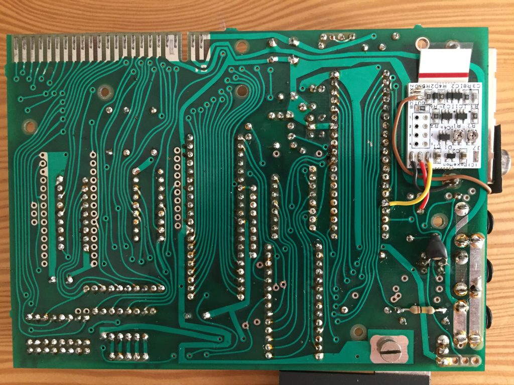
Bottom view 
Detailed bottom view
From the top you basically don’t see anything except the small brown cable that goes into the unused hole in the modulator housing to the connector (the original modulator connection just being unsoldered but left intact).
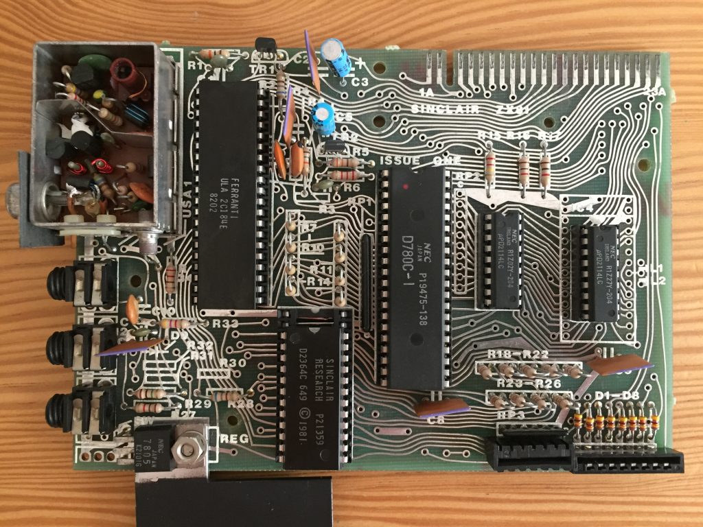
Top view, nothing really visible 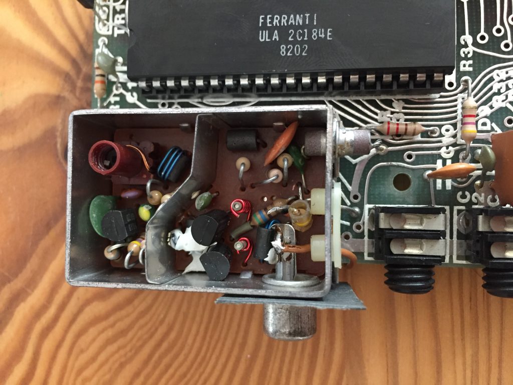
Detailed view of modulator
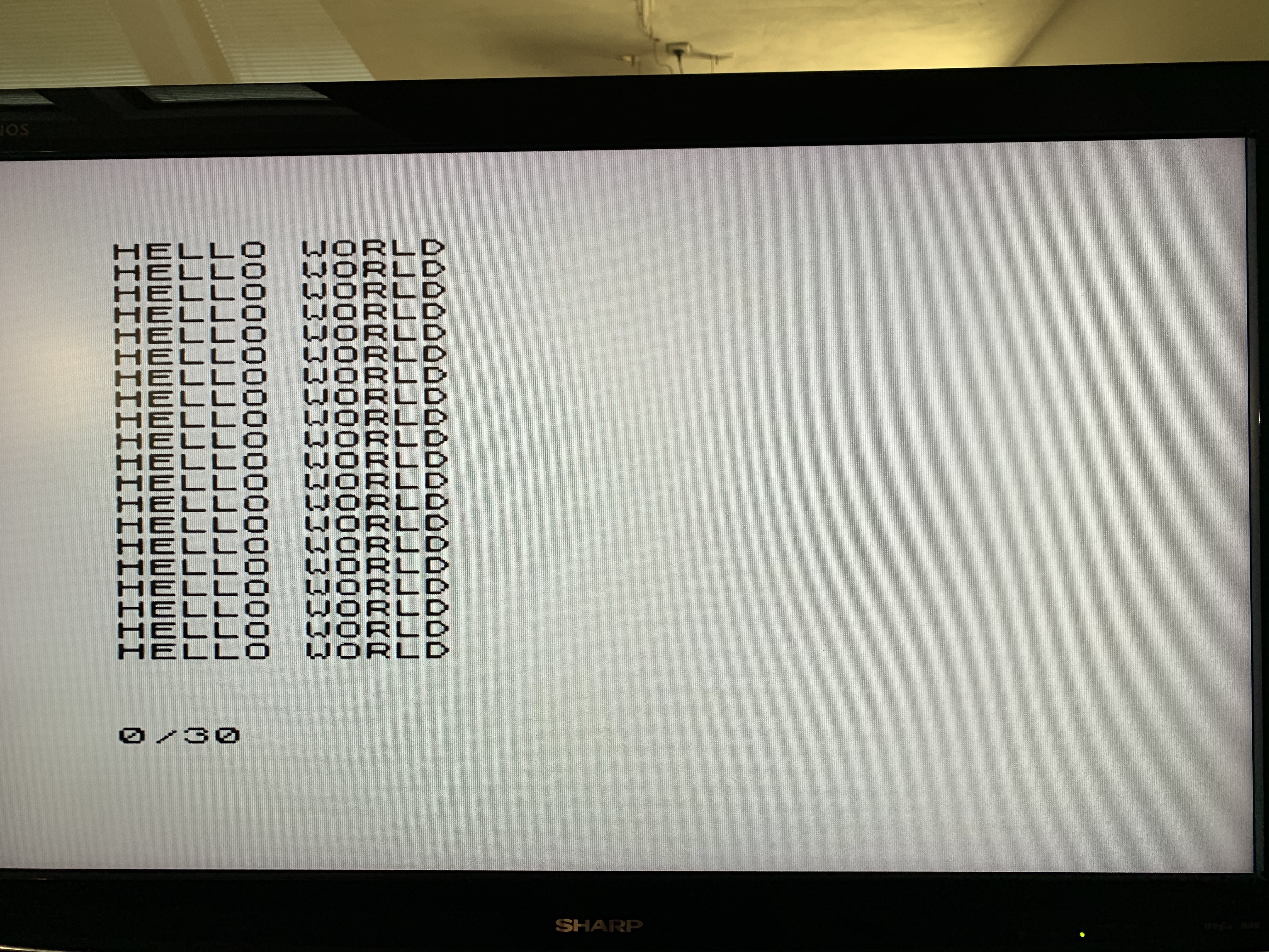
At first it didn’t show any picture. Even though it says that it comes pre-adjusted for the 1st edition ULA mine was apparently sufficiently different that the picture remained black. But not to worry, after playing with the two small potentiometers the screen came to life and voilà, the ZX81 now outputs a clean picture:
ZX-CCB can usually be found on SellMyRetro.