Yearly Archives: 2018

QL-SD news

(Summary at the end if you’re not interested in the details)

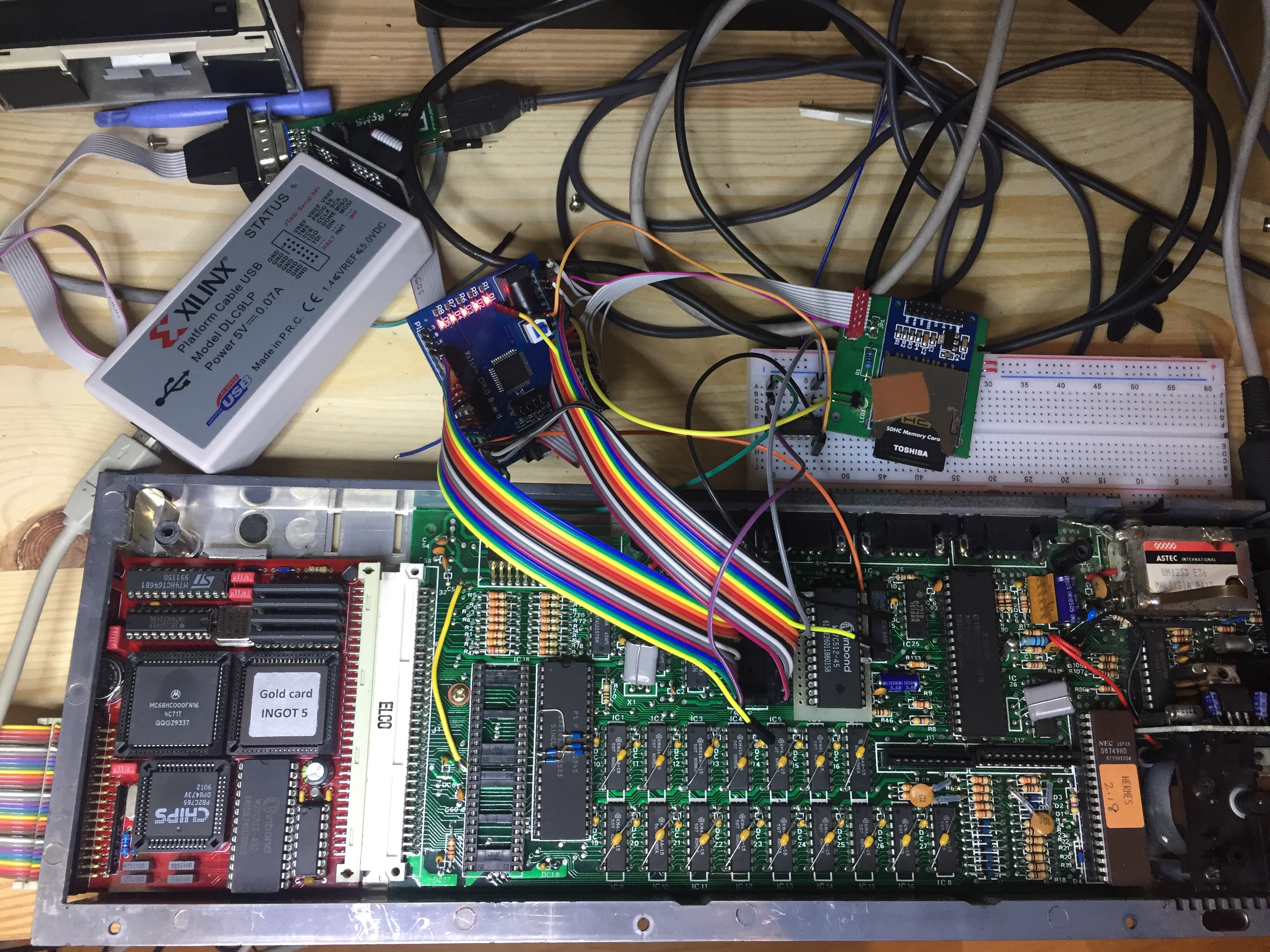
Some people know that I’ve been working for quite some time on making the QL-SD work with the late Stuart Honeyball’s masterpieces, the GoldCard and the SuperGoldCard. And I seem to have succeeded, but the way to success took a lot more time than I anticipated. A mix of simultaneous problems in the hardware connections, bus signals, driver software and CPLD chip made for quite a difficult debugging experience. Small changes in the CPLD code that should not have any logical impact made the thing not work anymore at all, etc. Hardware is weird! Good thing I don’t have hair anymore anyway.

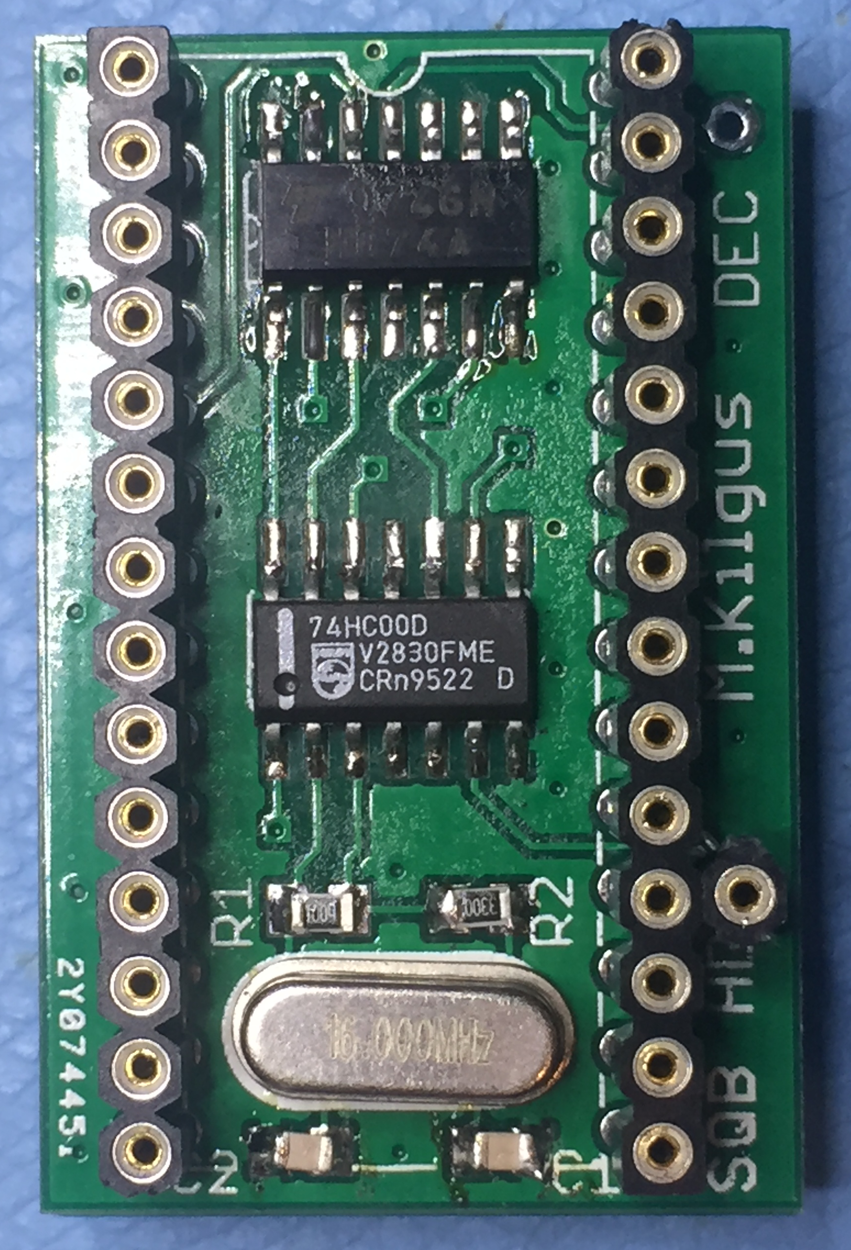
But now that the problems appear to be solved there is no supply of new QL-SDs to spread the joy! Dave mentioned he’s working on an external version, but I quite like the internal ones and quite frankly after all this work I didn’t mind the idea of generating at least some small revenue for my time for a change. So two weeks ago I decided to have a go myself and designed a new replacement board that is a bit easier to manufacture than the originals but other than that very similar. I ordered a batch of 50 gold plated PCBs on the good faith that they will simply work and yesterday DHL express delivered the precious cargo:

I soldered one prototype and, surprise surprise, it worked flawlessly from the get-go! Pure adrenaline 😉 The second board, made with lead-free solder this time, was a bit more stubborn but eventually succumbed to my superior solder skills (just kidding). Here’s a sneak peek:

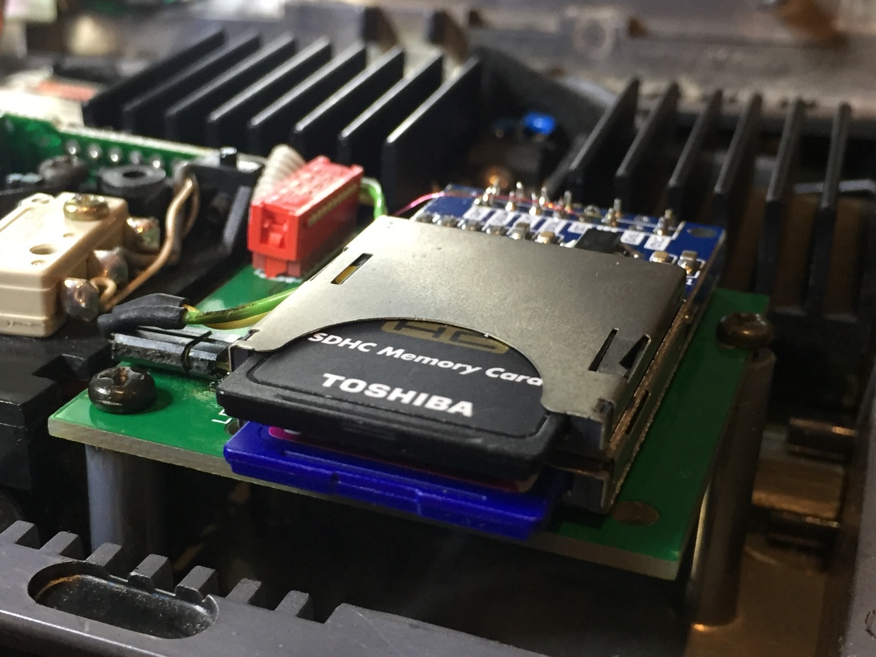
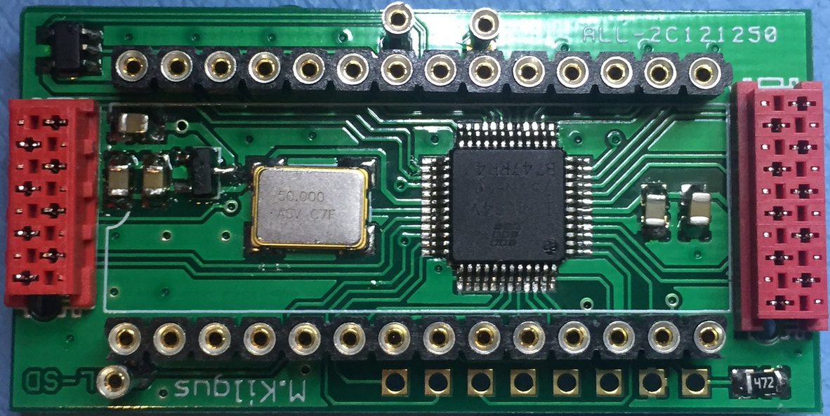
Connoisseurs will notice that I’ve used bigger traces and components on the PCB to make it easier to produce, the space is there after all. What I haven’t finalized yet is the design of the MDV daughter board, which is really trivial but I wanted to wait if my main board worked before I invested even more money! Also I had the idea to provide a dual-card board and even made a working prototype out of my existing QL-SD adapter:

QL-SD dual card adapterQL-SD dual card adapter

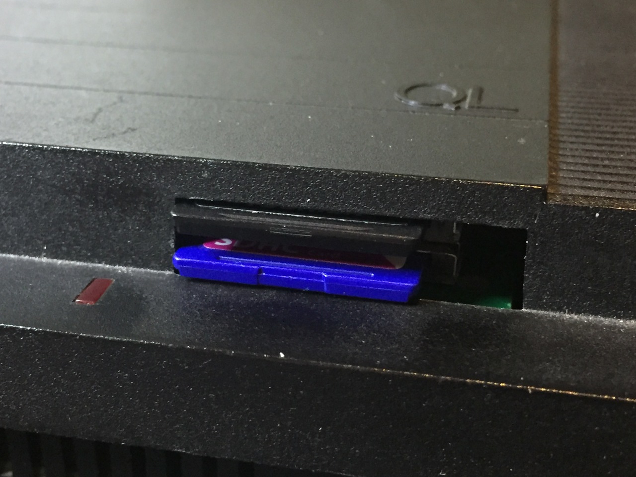
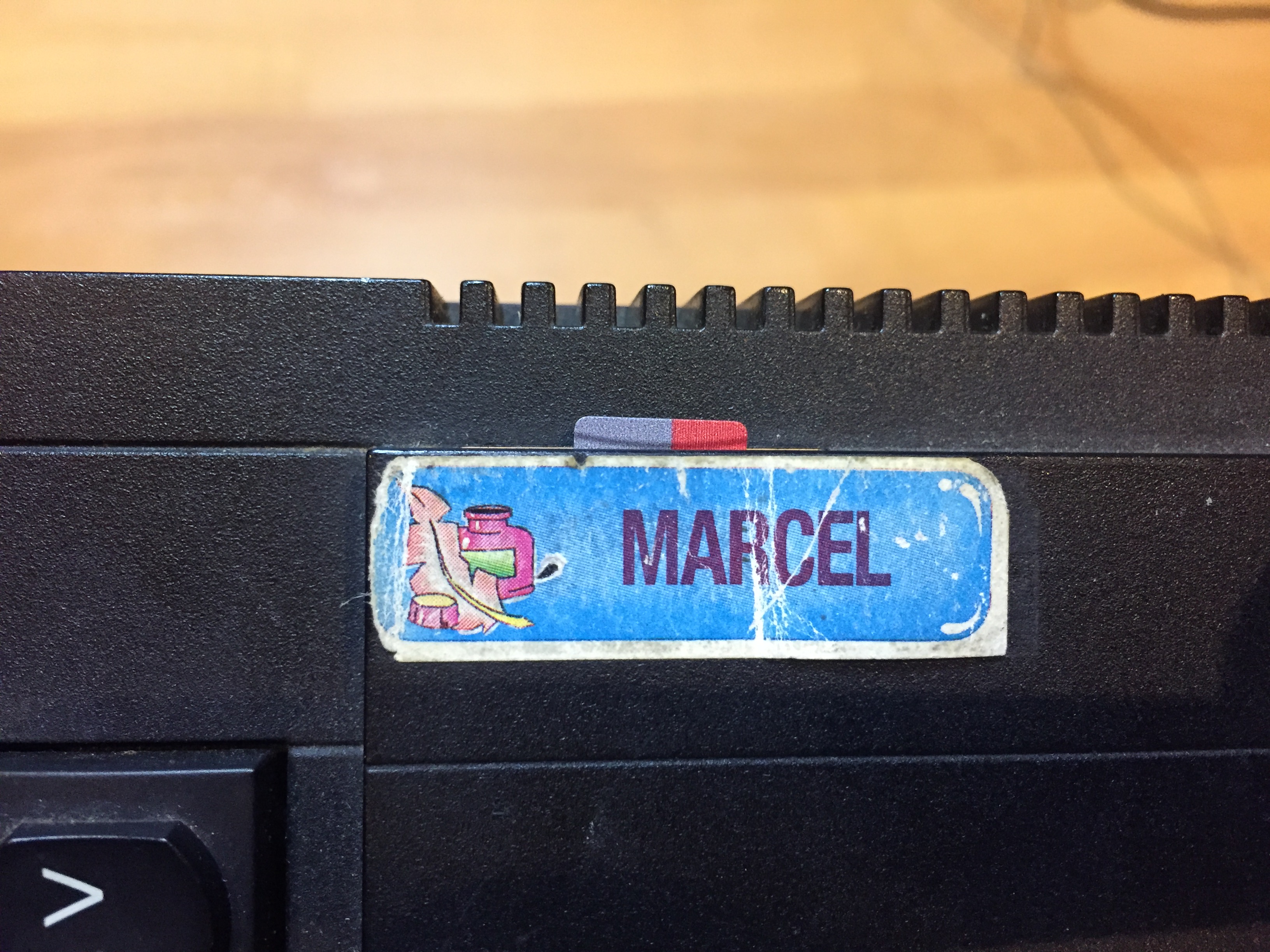
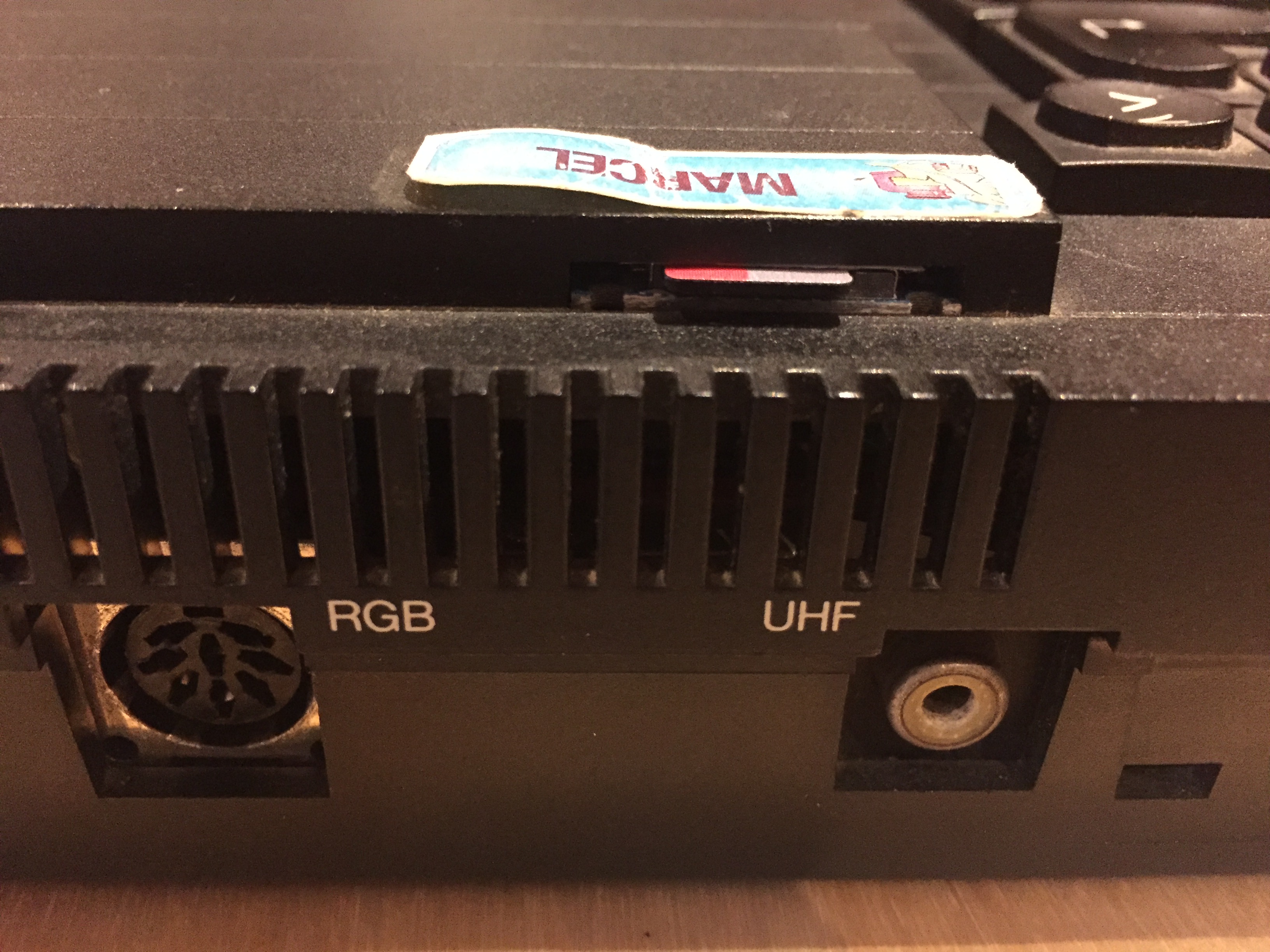
What I didn’t anticipate were the small rails holding down the MDVs in the top of the case, so the whole thing almost but doesn’t quite fit. I’m thinking about lowering the main PCB to be flush with the screw-posts but I’m not sure how mechanically sound this would be and if it’s really worth the trouble. Tell me if you’re interested! I also tried a completely different approach, but that was more a thing done in jest, using an existing ventilation hole in the QL case (that sticker was actually put onto my QL about 28 years ago 🙂 ):

TL;DR

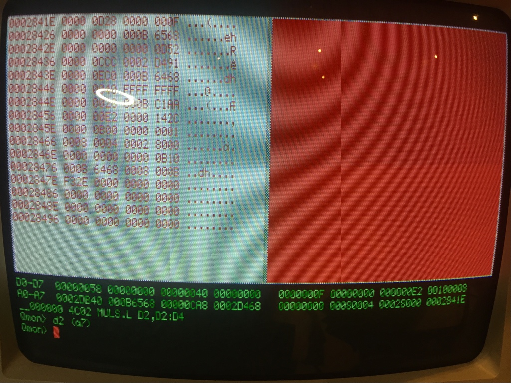
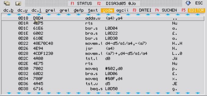
  • QL-SD works great now with GoldCard INGOT 5 including Tetroid clone (I think INGOT 6 already worked before) and SuperGoldCard. The original hardware only needs an update of the CPLD code for this. I will probably provide an update service for a fee, tell me if you’re interested.
  • I have submitted my fixes and changes to the driver to Wolfgang (thanks again Wolfgang, without his driver I wouldn’t have started my quest!), he said he will check them out soon.
  • I started producing a new batch of QL-SDs, though hand soldering them is a bit tedious and I will have to see if I can speed up the process. Price has yet to be determined.
  • I created a prototype dual-card adapter, but mechanically it’s not sound yet and even if these problems are overcome it might be difficult to produce. Anybody interested in this? It is 100% compatible with the original QL-SD, of course.

So, tell me if you’re interested or have any other comment.

Debugging Minerva

Martyn Hill recently discovered a bug in later versions of Minerva, but couldn’t quite pin it down. I thought it might be nice to write up a little tutorial about how I try to tackle these kind of problems.

The most important thing of course is being able to reproduce the problem, which was the hard part here as I haven’t had any networked QLs for 20 years. I didn’t remember any of the commands and devices used and somehow one ULA died along the way, which didn’t exactly help matters. But in the end I got it going and yeah, I could get it to crash:

QL1:
  NET 1
  SBYTES neto_2,131072,32768

QL2 (the one that will crash):
  NET 2
  LBYTES neti_1,131072

The “LBYTES” never returns here. The first thing to do in these cases is loading QMON and simply activating it

LRESPR flp1_qmon
qmon
Qmon> g

This way we will ideally break into the debugger if anything fishy happens. So, try the repro again and bingo:

Excuse the quality, at this point I didn’t know I will be writing about this, I made the picture just in case I need any data from it later in the process! Two things will look odd for people experienced in QMON, the “__000000” and the “MULS.L”. The first prefix “__” is an extension that displays addresses relative to the job base, which makes debugging jobs so much easier. In this case the JOB is SuperBasic, which has a start address of 0, so we’re actually at the absolute address 0 here. “MULS.L” is a 68020 instruction and now I can be glad I did this on a BBQL because this way the crash happened as early as possible. I think both the job-relative and the 68020 features were added to QMON by me some 15 years ago and were probably never released, but it doesn’t matter for this exercise.

The next step is to look at the stack, hence the “d2 (a7)”. There we see “00000D28”, which could potentially be a ROM address. In this case I have assembled Minerva myself so I have the corresponding _MAP file ready, which is invaluable when debugging assembler code:

SECTION   00000C9C  00000D78                                            IO_SERIO

          00000C9C  00000D78  SRC_MINERVA_IO_SERIO
                    00000CA8    IO_SERIO
                    00000CAA    IO_RELIO

This looks legit, so we open the source file “io_serio_asm” and also have a look into DISA to check which instruction exactly is there

Bingo, there is a jump instruction directly in front of it, so we’re at the right place. We look for it in the source code

callit
        movem.l d4-d5/a1/a4,-(sp) save our registers
        jsr     (a4)            call the test/fetch/send routine
        movem.l (sp)+,d4-d5/a1/a4 restore our registers
tstret
        tst.l   d0              ensure set ccr before returning
        rts

It jumps to a4 and, referencing the picture above, a4 is 0. We can also see the contents of the saved registers on the stack “0000000F” for D4, “00000000” for d5, “000b6568” for a1 and again “00000000” for a4. The next long word is “00000d52” which again looks like an address, so where are we coming from? Again, looking it up in DISA and then searching the instruction sequence in the source we end up at the label “headr1”

headr1
        bsr.s   io_pend         see if there is a byte available yet
        bne.s   setd1           if not, or there's a problem, return updated
        not.b   d1              check the value of the waiting byte
        bne.s   err_bp          error if it isn't $ff

Ah, so we were calling io_pend, let’s look at this code

io_pend
*        moveq   #0,d0           test routine is the first element
        bsr.s   vectest         set up test routine address
        bra.s   callit          go do it

Lau commented out the “moveq” because he thinks d0 is 0 here anyway. We have a look at “vectest”

vectest
        exg     a4,d0
        btst    #0,d0           test lsb of address register
        exg     a4,d0
        beq.s   vecrel          if zero, go do relative vector
        move.l  -1(a4,d0.w),a4  pick up serio's absolute vector
        rts
vecrel
        add.w   (a4),a4         add relio's relative vector to get absolute
        rts

where we see that D0 is used as an index but should be the same going out as going into the function. No we have a look at the QMON screenshot and see that D0 is actually “00000058”! So the assumption that it would be “0” doesn’t hold and this explains our crash. We include the “moveq” in the source code, reassemble and burn the EPROM and yes, it doesn’t crash anymore. Happy days 🙂

The whole process maybe took 10 minutes, it was actually a pretty straight forward. For sure it took a lot longer to write it up 😉 I know Martin has been working at this for quite a bit, so I thought I’d share my method in the hopes that more people can find and fix these kind of bugs in the future.

For everybody who is not at home assembling Minerva I have added an English and German version with the fix here:

Minerva 1.98 with I/O fix (English/German)

Clonetastic: QL-SD clone working with GoldCard clone

Every since I got my QL-SD interface I was annoyed with the driver support, especially on the PC side. I didn’t manage to fill the SD card without destroying the image one way or another. Then came Wolfgang Lenerz awesome QLWA compatible driver and now it works like a charm.

But only on my original QL, the QL-SD always had problems with the (Super)GoldCards of the world and especially with my Tetroid GoldCard clone, where it didn’t work at all. The general assumption was that the QL lines are too noisy and the chip employed on the QL-SD too fast so that all sort of trouble happens. To check for this I started building a QL-SD clone (thanks to Peter Graf for open-sourcing the hardware!) using a slightly older Xilinx XC9572XL architecture. But before I could finish that I finally did some measurements myself and found something interesting concerning my GoldCard:

When the ROM area is accessed the CPU puts the address on the bus and the motherboard generates the ROMOE (ROM Output Enable) signal. This is fed to the ROM chip, which in turn outputs the data for the address on the data bus. When the data read is finished, ROMOE is disabled again, the ROM stops driving the data bus and then the next address is put onto the address bus. Pretty simple. But now let’s look at this on the GoldCard, upper signal is ROMOE, lower signal is A0:

ROMOE/A0 signals

ROMOE/A0 signals

One can clearly see that the address line A0 begins to change even though ROMOE at this time is still high! This doesn’t harm much when accessing a ROM, it would just output some garbage which will be ignored anyway, but with QL-SD it’s a bit more complicated. This illegal state can trigger actions in the interface that were not requested by the software, especially when the driver code is executed from the ROM, too, as then obviously there are many more accesses to the ROM area. This also explains why some people apparently had more luck getting it to work when the driver was purely executed from RAM. Anyway, this can be fixed fairly easily. Problem is, I don’t have a Lattice programmer to change QL-SD, though one is on its way from China right now. But I did have my clone, so I worked with that:

Looks pretty wild, right? But what can I say, despite the long lines and everything, once my changes to the Verilog code were uploaded to the chip the interface began to work, without a single fault so far, even when the driver is executed from the ROM. With the original Verilog code my clone didn’t work at all, so it’s definitely not just the different chip.

Next step is waiting for my Lattice programmer to arrive (apparently today it was put onto an Airplane) and to reprogram the original hardware. I’m fairly confident that this will work, too, at least for the GoldCard. So far I still was not able to acquire a SuperGoldCard :-(, so I cannot tell in how far this would help there, too. Stay tuned!

Sandy SuperQBoard – now in HD!

A few years ago I got my old QL system out of storage and into working condition, but after 20 years of using QPC I completely forgot how much of a pain it really was. I never owned any of the Gold Cards, in fact all my BBQL hardware (640KB internal memory expansion, a 192kb battery powered static RAM-disc card (“MOS-Card”) and a Sandy SuperQBoard clone) were all hand-built by my late father, together with his work colleague Jochen Hassler (he jokingly called the Sandy clone “Herbert” card in the source and documentation, after my father).

Two major points I didn’t remember was how painfully slow the QL was and also that my setup could only read and write DD discs. Regarding the later point I found schematics of a HD capable version years ago, also designed by Jochen, and I went and checked them out. Though it’s not much, it took me a while to find all the differences in the schematics and understand what they did (remember, I’m not a hardware person!). I started to design some “upgrade board”, but many months passed without doing much of it and eventually I was able to buy one of the new Tetroid Gold Card clones (finally! Not the SGC I hoped to get one day, but at least progress 😉 ), so both of my problems were solved in principle (if only my QL-SD worked with it, but that is a topic for another time).

But the idea of a hardware upgrade for my old and trusty Sandy card still intrigued me and after Christmas I said “what the hell” and just tried it. This was the prototype:

And believe it or not, despite all the noise and the inherent problems with this solution it still worked 🙂 Not from the get go, there were some connection problems, but eventually. So I went back to my PCB design. Originally it was supposed to be a little board that can be fit somewhere on the Sandy board with lots wires to different parts of the board, but after realizing that almost all signals I need are already available on the WD1772 pins I designed it as an intermediate board between the controller board and the chip. In fact there is only a single additional line needed, the signal that ultimately selects between DD and HD, everything else is neatly handled by the design. So two days before new years eve I sent it to China for manufacturing and only 4(!!!) days later I got this back (shoddy soldering all mine):

Of course in my enthusiasm I forgot to include the decoupling capacitors for the two chips, but with the short lines, a huge ground plane on the bottom and the WD1772 capacitor so close-by it apparently doesn’t make any difference. So after all this time and effort this is what the result looks like and what can I say, it works like a charm:

Interestingly the same board could potentially be used to upgrade a TrumpCard, in this case however changes to the PAL and an upgraded TrumpCard driver would be needed, too. Unfortunately I currently don’t have any TrumpCard sources, even though considering that both use a WD1772 chip the difference to the Sandy driver should not be that great. The Sandy HD driver itself is a prototype that was also never released into the wild, I think, and it is unfortunately too big to still fit into 16kb (as it includes the ATR device), so combining it with TK2 is somewhat of a challenge. But then, nobody who every combined these two (except TT) had the sources before 🙂 So, let’s see what the future might bring…

Anyway, this was my little quest, thanks for reading and a happy new year!